Halbach magnets are interesting magnet arrays and can be easily build using cheap, off-the-shelf permanent magnets. Individual Halbach arrays create a static magnetic field. However, by combining two or more Halbach arrays that can be rotated with respect to each other it is possible to adjust the magnetic field strength at the center of the array.
Here, we present a two-ring Halbach array, capable of producing a variable magnetic field of 0.1-0.2 T based on off-the-shelf permanent bar magnets and a 3D printed support structure.
This is a simplified version of an array first described by Bauer et al. for Electron Paramagnetic Resonance (EPR) spectroscopy. It is based on the concept of NMR Mandhalas introduced by Raich et al. For more information and a complete theoretical description of the device check out the references below.
Introduction
Halbach Arrays
A Halbach array is a specific arrangement of permanent magnets that creates a strong and directed magnetic field. It was first proposed by Klaus Halbach, a physicist, in 1980 (see references below).
In a Halbach array, the individual permanent magnets are oriented in such a way that their magnetic moments reinforce each other on one side and cancel each other out on the other side, creating a uniform magnetic field.
Halbach arrays are often used in various applications, including magnetic levitation systems, magnetic bearings, and high-strength magnets for scientific research, or industrial applications. They can be employed in devices such as magnetic bearings for rotating machinery, nuclear magnetic Resonance (NMR) spectrometers, and magnetic resonance imaging (MRI) systems. The design is particularly useful in situations where a strong and focused magnetic field is required in a specific direction.
NMR Mandhalas
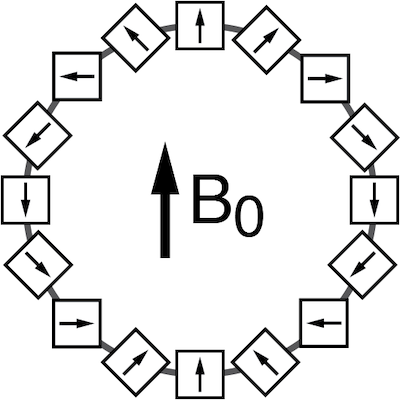
NMR Mandhalas (Magnet Arrangements for Novel Discrete Halbach Layout) are arrangements of permanent magnets using identical bar magnets, which are positioned and oriented based on analytical equations to create a magnetic field in a particular direction. An arrangement of 16 identical bar magnets is shown in the figure above. NMR Mandhalas can be constructed from a number of mangnets (n=4, 8, 16, 24, 32, …).
Using identical magnets, the overall field strength at the center of the array decreases when increasing the number of magnets due to the larger diameter required to arrange the magnets. However, the homogeneity gradually improves with an increasing number of magnets (except for an arrangement with n=8).
Halbach Arrays with Variable Magnetic Fields
A single Halbach array will create a static field at the center of the array. To be able to vary the magnetic field strength, a second array (second ring) can be placed on the outside. By rotating the outer ring with respect to the inner ring, the magnetic field strength can be varied. This concept was introduced by Bauer et al..
Building the Variable Halbach Array
CAD Model
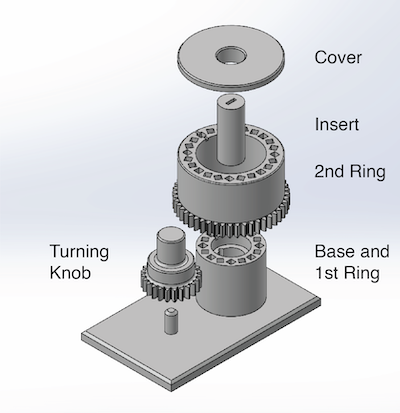
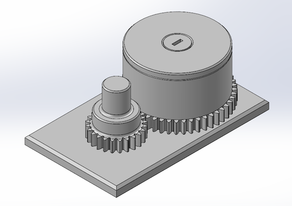
All parts for 3D printing were designed using SolidWorks. The complete magnet assembly consists of 5 different parts (links to .stl files for 3D printing are given in the parenthesis):
- Base and 1st Ring (Part 121005077) - Assembly base and 1st Halbach array.
- Turning Know (Part 121005155) - Knob to turn the 2nd ring to adjust the magnetic field strength at the center of the array.
- 2nd Ring (Part 121005152) - 2nd Halbach array with spur gear bottom. This part can be freely rotated to adjust the magnetic field strength.
- Insert (Part 121005245-01) - Variable insert. This part slides into the center of the array and can be modified. In the figure above, this insert is designed to hold a Hall probe to measure the magnetic field.
- Cover (Part 121005158) - Cover to close the array. Be careful when there are magnets inserted. Depending on how tight the magnets are sitting in the array, loose magnets can easily fly out of the array when rotating the 2nd ring.
To get started, you can either download the individual .stl files and start printing. If you would like to make changes to the design you can also download a zip archive with the complete SolidWorks CAD model.
3D Printing Files
A complete assembly for 3D printing can be downloaded here. Alternatively, the individual .stl files can be downloaded from the section above.
All parts were printed on an Ultimaker 2+ using an ABS filament and 20 % infill for the print.
Assembly
Be Careful when assembling the arrays. I recommend to insert the magnets into the individually support structures (rings) separately, before sliding the 2nd ring over the 1st ring. Depending on your printer settings some magnets can be loose and can easily fly out of the array.
Bar Magnets
The magnet array uses Neodymium Block Magnets from KJ Magnetics, Inc.. Here, I’m using the BC22 Magnets. They are 3/4" by 3/4" by 1/8", with a surface field of 4759 G. The magnets are magnetized along the short axis (Thru Thickness). You will need a total quantity of 40 magnets to complete the array. The total costs of the magnets is about $24.
A picture of the assembled variable Halbach array is shown below. Be careful when the cover is not on top of the assembly.
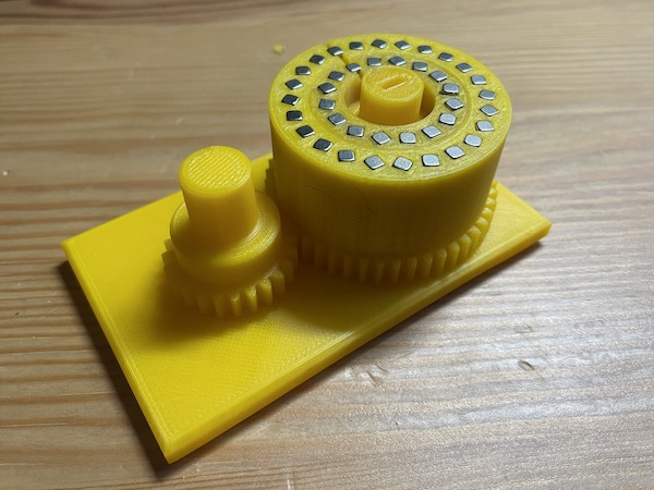
Note: In general, the turning knob is not required and can be omitted. This was more of a personal exercise to learn how to design spur gears in a CAD program. In a future, I plan to replace the knob with a stepper motor to remotely control field strength.
Evaluating the Variable Halbach Array
Magnetic Field Strength at the Center of the Array
Once the array is assembled it is time to evaluate the magnetic field strength and its dependence on the orientation of the outer ring. For this I used a Gauss Meter from Lake Shore Cryogenics (Model 421) with an transversal probe that is inserted into the center insert of the magnet array (hence the rectangular slot). The magnetic field strength as a function of the angle of the outer ring with respect to the inner ring is shown in the figure below.
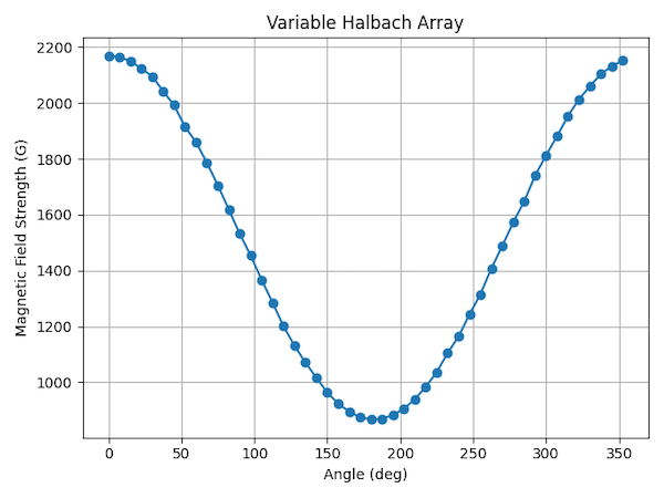
From these measurements a maximum magnetic field strength 2170.1 G is observed when both rings are aligned in the same direction. Turning the outer ring by 180º with respect to the inner ring results in a minimum magnetic field strength of 868.8 G.
Note: The original post stated that the field varied between 2 and 1 T. Thanks to Robert Lown for pointing out the mistake. Checking my notes, the variation is 2 to 1 kG.
Magnetic Field Homogeneity
At this point, I have not evaluated the homogeneity of the magnetic field at the center of the array, since this is not a trivial task. In general, I do expect a decent homogeneity, however, the off-the-shelf bar magnets will for certain have some field variations, which will lead to field inhomogeneities. To improve the homogeneity the original design by Bauer et al. has a third outer ring.
The goal of this project was to simply create a first working prototype of the variable field Halbach array. In the future I do plan to use this array for Nuclear Magnetic Resonance (NMR) experiments, at which point the design will be revisited and, if necessary, improved.
For now, have fun exploring this fun little device.
References
- Halbach, K. “Design of Permanent Multipole Magnets with Oriented Rare Earth Cobalt Material.” Nuclear Instruments and Methods 169 (February 1, 1980): 1–10. http://dx.doi.org/10.1016/0029-554X(80)90094-4.
- Raich, H., and P. Blümler. “Design and Construction of a Dipolar Halbach Array with a Homogeneous Field from Identical Bar Magnets: NMR Mandhalas.” Concepts in Magnetic Resonance Part B: Magnetic Resonance Engineering 23B (2004): 16–25. https://doi.org/10.1002/cmr.b.20018.
- Soltner, H., and P. Blümler. “Dipolar Halbach Magnet Stacks Made from Identically Shaped Permanent Magnets for Magnetic Resonance.” Concepts in Magnetic Resonance Part A 36A (2010): 211–22. https://doi.org/10.1002/cmr.a.20165.
- Bauer, C., H. Raich, G. Jeschke, and P. Blümler. “Design of a Permanent Magnet with a Mechanical Sweep Suitable for Variable-Temperature Continuous-Wave and Pulsed EPR Spectroscopy.” Journal of Magnetic Resonance 198 (2009): 222–27. http://dx.doi.org/10.1016/j.jmr.2009.02.010.
Disclaimer
- This document describes the OpenHalbachArray
- This devices uses strong permanent magnets. Be careful when assembling this device
- Making the OpenHalbachArray is entirely on your own risk. Bridge12 cannot be held responsible for any damage done to any equipment as a result of testing this device
- Please make sure to read these instructions carefully before making this device
This is teaching equipment. By no means should this low-cost Halbach Array compared with any high-end Halbach arrays.