Quasi optical (QO) systems are often used in high-field EPR and DNP systems to separate the incident microwave beam from the reflected beam. Furthermore, quasi optics is a versatile technology to build attenuators, universal polarizers, and beam splitters. This introduction gives an overview of the basics of quasi optics, its application and design considerations.
Most researchers are familiar with the concepts of Geometrical Optics which can be used in the limit of λ → 0. In this case lenses, mirrors and apertures are large compared to the wavelength and the effects of the actual wavelength can often be neglected.
The concept of quasioptics is used in an area when the dimension of the beam and components is several multiples of the wavelength. For example, at 263 GHz the wavelength of the radiation if λ = 1.14 mm. When using a Gaussian beam launcher with an aperture of 1/2 inch (12.7 mm) the aperture is a factor 11 larger compared to the wavelength.
Why Quasioptics?
At microwave frequencies > 140 GHz discreet components such as circulators, directional couplers, or beam splitters tend to have large insertion losses or simply aren’t available. For example, while at X-band frequencies (~ 9.5 GHz) losses in a WR-90 waveguide are about 0.1 dB/m, losses for a WR-10 waveguide, used to transmit microwave power at 95 GHz are as high as 3 dB/m. At 263 GHz, using a WR-4.3 waveguides, losses are typically > 15 dB/m. An alternative for power transmission are Corrugated Waveguides to propagate high-frequency microwave radiation. In addition, microwave power can be transmitted essentially loss-less as a free-space Gaussian beam in the TEM00 mode.
As mentioned above, one condition to employ QO is that the size of components and apertures must be much greater than λ. However, a Gaussian beam diverges when travelling through space and any surface (e.g. mirror, wire grids) need to be sufficiently large. To propagate a beam over larger distances, the beam needs to be refocused periodically. This can be achieved using metallic surfaces (mirrors) and the dominant contribution to losses are diffraction losses. Nevertheless, the losses experienced in a free-space beam QO system are typically just a fraction of a dB.
Gaussian Beam Propagation
The treatment of a free-space Gaussian microwave beams is similar to the description used in laser spectroscopy (for example see Kogelnik et. al). The description of Gaussian beams used in QO systems is often limited to the TEM00 mode because higher order modes have different propagation properties and “leave” the system. However, to understand losses in a system higher order modes sometimes need to be considered because mode conversion can be a major contributing factor to system losses.
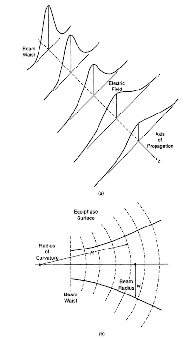
A Gaussian beam is characterized by its beam waist radius ω0 and its radius of curvature R. A great deal of confusion exists in the literature whether the beam waist (diameter) or the beam waist radius is considered. Here, ω0 will always denote the beam waist radius. The figure to the right shows the beam propagation in free space along the z axis. At the launching aperture, the beam waist radius is given by ω0 and R = ∞. When the beam is propagating along the z axis, the beam waist radius increases and the intensity at the center decreases.
The lower part of the figure shows the equiphase surface (dashed lines). At the launching aperture, the radius of curvature is R = ∞. R will decrease while the beam is propagating. If the beam is to captured by a (receiver) horn, the beam first has to be focused so that the phase front of the beam is again flat (R = ∞), otherwise losses will occur.
Quasi Optical Components and Layout
The most commonly used components in a QO systems are Mirrors, free-standing wire grids, polarization transforming plates, and launchers. In the following a brief description of these components is given.
A very useful and practical concept to design QO system was introduced by Lesurf in the 1990s. Here, QO components are designed as cubes, or half-cube devices. In general, a focussing mirror has equal input and output focal length. Flat mirrors can be made by simply cutting the cube along its diagonal, and grids can be mounted on this diagonal face.
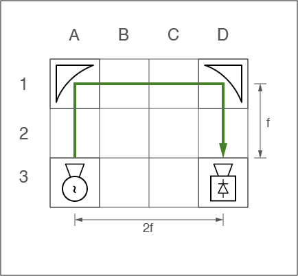
These cube elements are than arranged on a grid. This concept is shown in the figure to the right. To build frequency independent systems, quasioptics are typically arranged as a Gaussian Telescope. This is important when designing frequency independent systems. The magnification of the quasioptics is often unity and therefore the beam waist radius of the input and output beam is identical. Focusing mirrors are arranged in pairs and depending on the focal length of the mirror typically every third or fourth cube on the grid is occupied by a focusing mirror. This leaves two or three positions between the focusing mirrors to place other elements such as grids.
An example of such an arrangement is given in the figure to the right. The focusing mirrors are located at position A1 and D1. The source is located at A3 and the receiver at D3. This leaves positions A2 and D2 to place for example grids to clean up the beam. Positions B1 and C1 are available to put other polarizing elements.
QO Mirrors
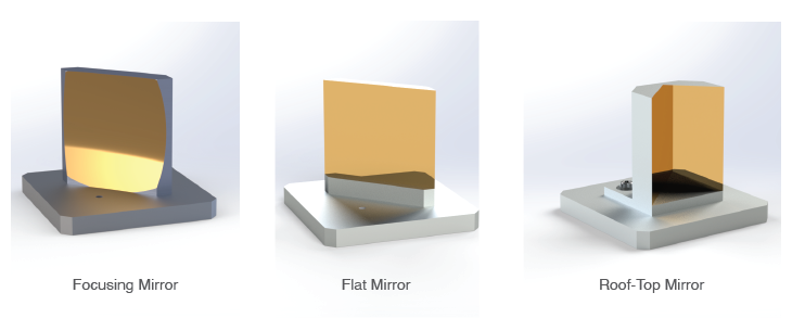
A central component of all quasi-optical systems are mirrors. While the Gaussian beam is propagating through the system it diverges and needs to be frequently refocused. This can be done using lenses, however, to reduce losses due to absorption of the lens (elliptical) off-axis focusing mirrors are used (see Figure above, left side). The disadvantage of off-axis mirrors is that the propagation direction of the beam changes by 90 degree. Flat mirrors (see Figure above, middle) can be used to change the propagation by 90 degree between refocusing mirrors.
A special mirror is the roof-top mirror (see Figure above, right side). This mirror will reflect the beam back towards its original propagation direction. Depending on the direction of the E-field vectors, its direction is either unaltered (E-field vertical) or the direction is flipped by 180 degree (E-field horizontal). Roof-top mirrors are used for example in the Martin-Puplett-Interferometer (MPI).
Wire grids
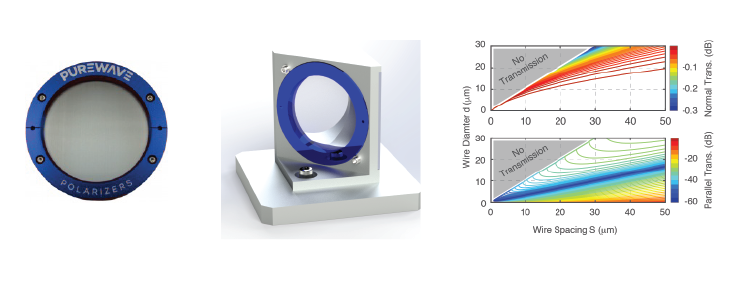
Another component in every quasi-optical systems are free-standing wire grids. The are used as low-loss polarizing elements and have many applications such as as beam splitters, couplers, or variable attenuators. A typical free-standing wire grid is shown in the figure above (left side). These grids are made from conductive tungsten wire and are not supported by a substrate. Grids are characterized by the diameter of the tungsten wire and the spacing and for QO for THz applications a wire diameter of 10 µm separated by 25 µm is very common.
The grid is often mounted on the diagonal of a cube as shown in the figure above (middle). The free-standing wire grid array will reflect the incident beam if the E-field is polarized parallel to the wires, and transmit radiation if the E-field is polarized orthogonal to the wires. In this way, a wire grid acts as a polarizing element both in transmission and reflection, this is shown in the figure above (right side). For the wire grid to work efficiently, the spacing between the wires needs to be less than the wavelength of the radiation. This effectively puts a limit on the maximum frequency for a given wire grid.
Launchers
To launch the microwave radiation as a Gaussian beam into the quasioptics horn antennas (or launchers) are used. These launchers produce a Gaussian beam at their aperture with little or minimized side lobe content. Corrugated horn antennas are most commonly used and the the Gaussian beam waist at the horn aperture is given by ω0 = 0.6435*a, with a the radius of the horn aperture.
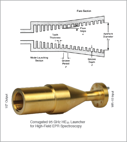
To the right a typical corrugation profile for a Gaussian beam launcher is shown. The launcher is made of several sections. Typically, the first section is a transition from a rectangular waveguide (e.g. WR-10) to a circular waveguide section. The following sections have corrugations with variating depths (from λ/2 to λ/4) and and up taper section to the desired aperture.
Below the schematic is a Bridge12 95 GHz launcher shown. The launcher converts the TE10 of the rectangular waveguide mode to the HE11 mode, the dominant mode inside corrugated waveguides. Th e HE11 mode couples with ~ 98 % efficiency to the free-space Gaussian beam mode.
Further Information
Literature
There is a large amount of further information about quasioptics available. However, not many sources actually mention applications in magnetic resonance. Therefore, the literature is sometimes difficult to understand. In the following a selection of books, review articles, and research papers is given that are more geared towards the intersted reader, rather than the hardcore electrical engineer.
Books
- Goldsmith, Paul F. Quasioptical Systems: Gaussian Beam Quasioptical Propagation and Applications. IEEE Press/ Champman & Hall Publishers, 1998. Link
- Lesurf, J. C. G. Millimetre-Wave Optics, Devices, and Systems. Bristol, England ; New York: A. Hilger, 1990.
Review Articles
- Earle, Keith A., Jack H. Freed, and David E. Budil. “Millimeter Wave Electron Spin Resonance Using Quasioptical Techniques.” In Advances in Magnetic and Optical Resonance, edited by S. Warren Warren, Volume 19:253–323. Academic Press, 1996. https://www.sciencedirect.com/science/article/pii/S1057273296800192.
- Earle, K. A., and J. H. Freed. “Quasioptical Hardware for a Flexible FIR-EPR Spectrometer.” Applied Magnetic Resonance 16 (February 1, 1999): 247–72. https://doi.org/10.1007/bf03161937.
- Budil, David E., Zhebo Ding, Greg R. Smith, and Keith A. Earle. “Jones Matrix Formalism for Quasioptical EPR.” Journal of Magnetic Resonance 144 (2000): 20–34. http://dx.doi.org/10.1006/jmre.2000.2024.
- Gullá, Andrea F., and David E. Budil. “Engineering and Design Concepts for Quasioptical High-Field Electron Paramagnetic Resonance.” Concepts in Magnetic Resonance Part B: Magnetic Resonance Engineering 22B (2004): 15–36. https://doi.org/10.1002/cmr.b.20014.
- Murphy, J. Anthony, and Créidhe O’Sullivan. “Terahertz Optics.” In Terahertz Spectroscopy and Imaging, edited by Kai-Erik Peiponen, Axel Zeitler, and Makoto Kuwata-Gonokami, 29–56. Berlin, Heidelberg: Springer Berlin Heidelberg, 2013. https://link.springer.com/chapter/10.1007/978-3-642-29564-5_2.
- O’Sullivan, Créidhe M., and J. Anthony Murphy. Field Guide to Terahertz Sources, Detectors, and Optics. SPIE, 2012. https://doi.org/10.1117/3.952851.
- R. J. Wylde. “Millimetre-Wave Gaussian Beam-Mode Optics and Corrugated Feed Horns.” Microwaves, Optics and Antennas, IEE Proceedings H 131 (1984): 258–62. https://doi.org/10.1049/ip-h-1.1984.0053.