
Loop-Gap Resonators (LGRs) are a class of microwave resonators/cavities that are frequently used in Electron Paramagnetic Resonance (EPR) spectroscopy. LGRs were introduced in the 1980s by Hyde et al. as an alternative to the widely used rectangular TE102 or the cylindrical TE011 EPR cavity.
LGRs have many advantageous such as:
- a large filling factor
- a large conversion factor
- a low quality factor (Q)
- can provide large uniform microwave fields across the sample
These attributes make LGRs especially interesting for pulsed EPR spectroscopy, a technique that requires large conversion factors but a low Q to avoid problems due to cavity ring-down. For more information on LGRs take a look at this publication:
Rinard, George A., and Gareth R. Eaton. “Loop-Gap Resonators.” In Biomedical EPR, Part B: Methodology, Instrumentation, and Dynamics, edited by Sandra R. Eaton, Gareth R. Eaton, and Lawrence J. Berliner, 19–52. Boston, MA: Springer US, 2005. https://link.springer.com/chapter/10.1007/0-306-48533-8_2.
An Open-Source PCB-based LGR Resonator
LGRs are not simple to fabricate. The fabrication process often requires high-precision machining methods such as Electric Discharge Machining (EDM), a technique that is often used when tolerances need to be very tight. However, standard machine shops often don’t have this capability and parts often have to be sent out to specialized machine shops.
We present a simple method to build an LGRs from printed circuit boards (PCBs). The resonator is easy to assemble and does not require any specialized machining techniques. The resonator is constructed from a set of PCBs, off-the-shelf hardware components, and 3D printed parts.
The resonator design is completely open source. All files including the CAD model, the Bill of Materials (BOM) and assembly instructions can be found at:
OpenPCBLGR
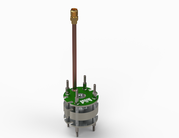
The OpenPCBLGR is assembled from just a few components: 1) a stack of PCBs, 2) off-the-shelf hardware, 3) 3D printed parts, some wire and standard electrical connectors. The coupling loop itself is made from a PCB and is soldered to the end of an SMA cable. The coupling loop couples to one of the return loops of the resonator and by moving it up and down the resonator coupling can be adjusted.
A Stack of PCBs
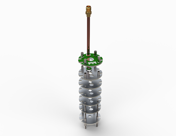
The OpenPCBLGR is a 3 loop, 2 gap (3L2G) resonator. It is made of individual PCBs that are stacked on top of each other. Two more PCBs are located above and below the resonator to create a void above the LGR structure. A 3D printed shield, covered on the inside with copper tape shields the electrical field inside the resonator from environmental disturbances.
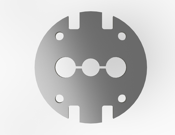
Made from Individual PCBs
At the heart of the resonator are a stack of individual PCBs with the actual LGR structure cut into it. The interior walls as well as the top and bottom of the individual PCBs are then covered/plated with copper and a protective tin layer is applied. These are standard techniques when fabricating PCBs.
No solder mask is applied to the top and bottom of the PCB to make sure a good electrical connection is made between the different layers.
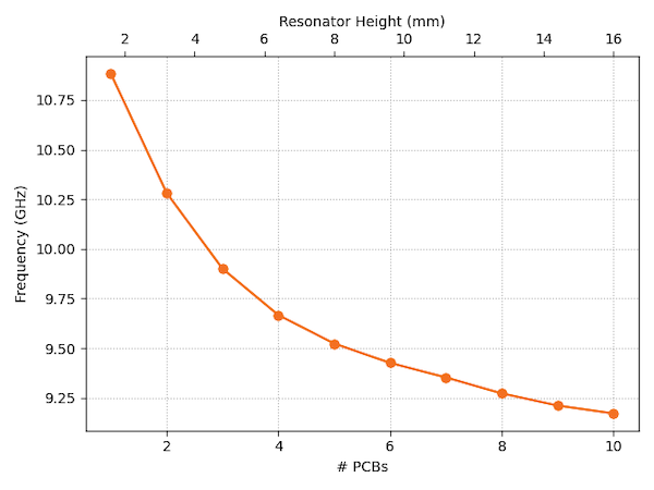
Changing the Resonator Frequency
The resonator frequency depends on the overall height of the sample loop. By varying the number of individual PCBs that make up the resonator body the frequency of the resonator can changed.
If only a single PCB is used, the resonance frequency is quite high (> 10.75 GHz). By adding more PCB layers the frequency can be lowered. When using a stack of 10 PCBs the resonator frequency is below 9.25 GHz.
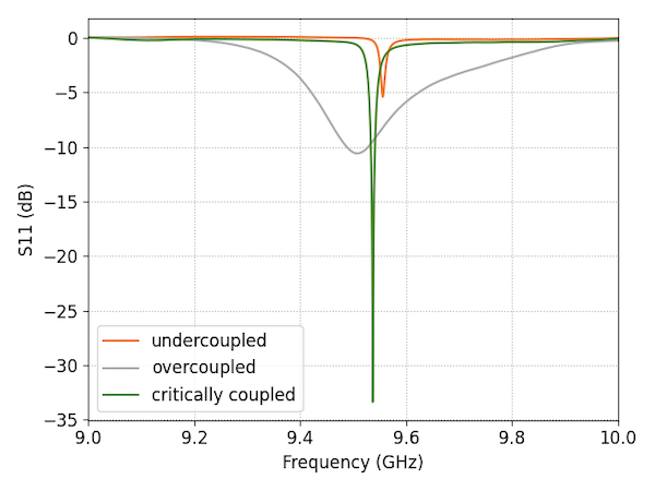
Coupling to the LGR
By changing the height of the coupling loop the resonator coupling can be changed from undercoupled, to critically coupled to completely overcoupled.
This will allow cw EPR experiments (crictially coupled resonator) as well as pulsed EPR experiments (overcoupled resonator).
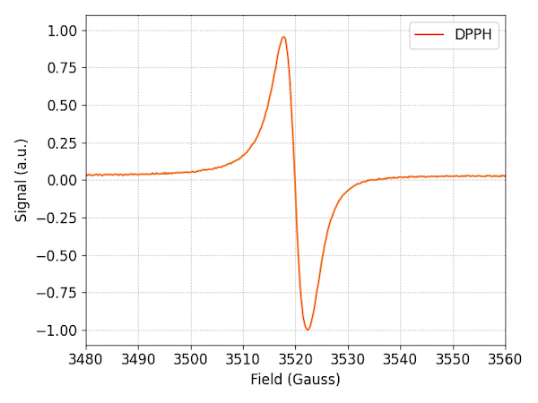
EPR Spectroscopy
Finally, here is a cw EPR spectrum recorded using the OpenPCBLGR resonator. The sample is neat DPPH and the EPR spectrum is recorded at room temperature using a home-built x-band EPR spectrometer.
Disclaimer
- This document describes the OpenPCBLGR an Open-Source resonator for continuous wave (cw) x-band EPR spectroscopy
- Assembling and using the OpenPCBLGR is entirely on your own risk. Bridge12 cannot be held responsible for any damage done to any equipment (e.g. test equipment or spectrometers) as a result of testing this resonator
- Please make sure to read these instructions carefully
Resonators for Electron Paramagnetic Resonance (EPR) spectroscopy are intricate devices and expectations in terms of performance/sensitivity are very high. The resonator described in this project is a resonator for teaching, not to perform ground-breaking experiments on extremely diluted samples. The resonator is intended to teach the fundamentals of LGRs to interested researchers (graduate students or postdocs).
By no means should this low-cost EPR resonator (< 100 $) be compared with an EPR resonator that can cost several ten thousands of dollars. This is a teaching tool, not a high-end resonator.