Compact QO Systems
Discreet microwave components (e.g. circulators) are nowadays available up to 130 GHz and unless very high port isolation (> 50 - 60 dB) is required, these components are totally acceptable for EPR/DNP spectroscopy. Limiting the lowest operating frequency of our QO components to 140 GHz the Bridge12 QO system uses a grid size of 2.5 in. by 2.5 in., resulting in small, compact QO systems. The upper value of the operation frequency is limited by the free-standing wire grids, which in our case is several THz. Therefore, a typical QO circulator has typically a foot print of less than 12 in. by 12 in.
Low-loss Circulators
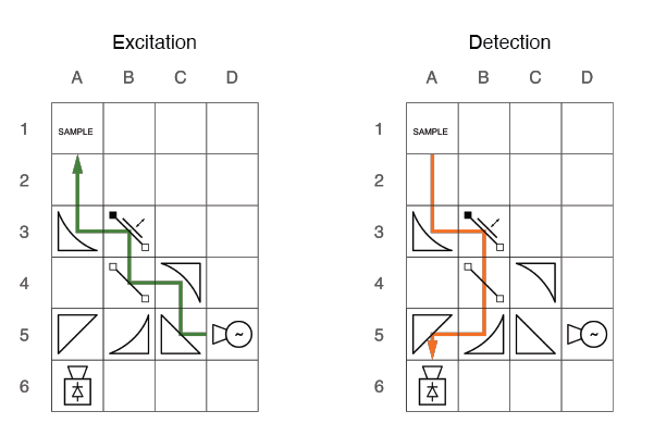
At the heart of every EPR spectrometer is the circulator. Its purpose is to direct the incident microwave radiation towards the sample, the reflected power towards the detector, and provide high isolation between the source and detector. At frequencies < 130 GHz discreet microwave components can be used. However, at higher frequencies the insertion losses become very large and low-loss QO is preferred. In the QO circular a combination of grids, reflectors and dielectric plates is used for the task. For magnetic resonance spectroscopy two concepts can be used. The first one uses a Faraday Rotator (FR) to rotate the direction of the linearly polarized E-field. The second one uses a Polarization Transforming Reflector (PTR) to convert the linearly polarized beam into a circularly polarized beam (for details see the PTR product page). While the FR has an insertion loss of typically > 2-3 dB, the PTR has much lower losses ov < 0.5 dB.
Modular Quasi-Optical Systems
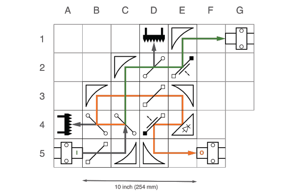
Most researchers are familiar QO circulators used in high-field EPR spectroscopy. However, QO is capable of much more. The schematics to the right shows a QO beam splitter with universal polarization control and the possibility to individually control the output power in each arm. Microwave power enters the system at A5 and is directed to G1 (port 1) and F5 (port 2). The grids can be motorized to allow for active feedback control of the output power. All excess power is dissipated in the micorwave absorbers located in D1 and A4. This system can for example be used to deliver microwave power from one source (e.g. gyrotron) to two DNP-NMR spectrometers.
Technical Specifications
- Minimum operation frequency: 140 GHz
- Maximum operation freqeuncy: < 2 THz
- All components can be placed on a 2.5 in. by 2.5 in. grid.