I recently came across a short tutorial how to “Print NMR coils for NMR spectroscopy” on Youtube and I decided to give it a try. The results are pretty amazing.
Materials/Tools
The following materials are required:
- Vinyl cutting machine: I used a Silhouette Cameo 4 with the regular AutoBlade and a light sticky matt.
- Software: The CAD model of the coil is created in Autodesk Inventor. I used a parameterized model but any CAD software that can export the face of a sketch in dxf format will do. To cut the coil I used the software that came with the Cameo vinyl cutter. It is pretty straightforward to use. There are plenty of tutorials available online (you have to sit through a couple of “home-crafts” projects though …)
- Copper Foil Tape: The tape is available on Amazon or DigiKey. The copper foil is about 2 mil. thick (~ 50 µm ) and 1 inch wide.
- Transfer Tape: I used Clear Transfer Tape for Vinyl from TapeManBlue, available on Amazon.
In addition to the above mentioned materials a scalpel (I prefer a #11 blade), pointy tweezers, scissors, rubbing alcohol for cleaning, a steady hand, and patience is required.
Step-by-Step Instructions
CAD Model
Let’s start with a CAD model of the coil. Here, I use Autodesk Inventor to create the model of the coil. In this case, the model is fairly elaborate and allows for scaling of the coil dimensions. To get started, check out the coil dimensions of a three turn saddle coil shown in Mispelter et al. “NMR Probeheads for Biophysical and Biomedical Experiments”, (chapter 8, page 506, figure 8.26). The coil has some decent dimensions to get started (e.g. an ID of 11.4 mm) and is straightforward to cut on a vinyl cutter. I have cut traces down to 0.5 mm width, however, my advise is to start with larger traces to fine tune the cutting parameters before proceeding to more challenging coil designs.
If you don’t have access to a CAD software, you can also create the coil directly in the software that comes with the vinyl cutter.
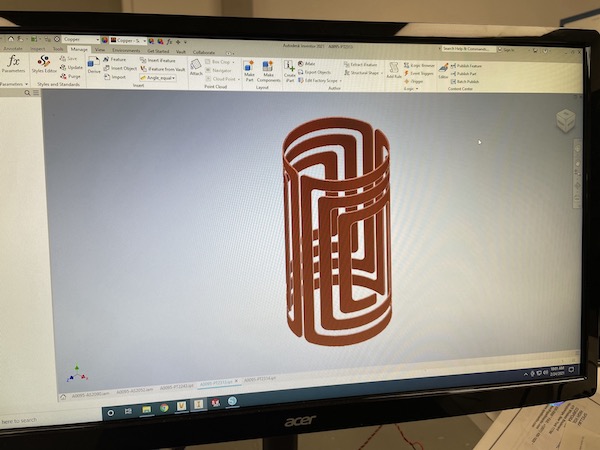
Figure 1: CAD model of the NMR coil.
Once the CAD model is created you have to export the face of the coil as a dxf file. This file can be directly imported into the software that is used by the vinyl cutting machine. In Inventor all you have to do is right-click on the face of the coil, and then select “Export face As …” to save the dxf file.
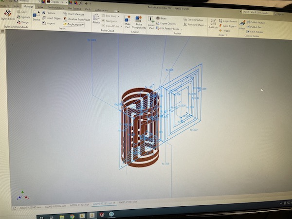
Figure 2: Exporting the face of the NMR coil as dxf file.
The dxf file can be readily imported into the cutting software. In the case of Silhouette Studio, the correct shape of the coil is imported, but the overall size is not correct. To get to the correct size of the coil, the sketch needs to be manually scaled to the correct dimensions. For that make sure to hit the little lock sign to preserve the proportions of the coil. In my case, I created a reference dimension in the sketch that can then be used in the cutting software to scale the sketch to the correct dimensions. Every software is slightly different and it requires a bit of tinkering to get the correct dimensions.
To make removing of excess material and lifting off the coil from the backing tape easier, I also cut a rectangular box around the coil. I added this box in the cutting software of the vinyl cutter, not in the CAD software.
Once everything is scaled properly it is time to start cutting.
Preparing the Cutter
To cut the coil, the copper tape has to be placed on the cutting matt. Don’t remove the backing paper of the copper tape. Cut an appropriate size of the tape and place it on the matt. Avoid any air bubbles. I use a light sticky matt to make it easier to lift it off the matt easily. Use a metal or plastic tube (e.g. 1 inch in diameter) and roll it over the copper tape to make sure it sticks well to the matt. Don’t press down on it too hard, otherwise it will be more difficult to lift of the backing paper from the matt.
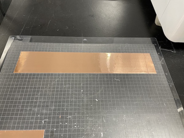
Figure 3: Place copper tape on sticky matt.
Once the copper tape is placed on the matt the matt is ready to be loaded into the vinyl cutter.
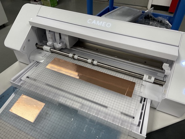
Figure 4: Load matt into cutting machine.
Cut!
Once the cutting matt is loaded into the cutter it is time to cut the coil. Follow the instructions for your specific vinyl cutter to start the job. You probably have to do a couple of test runs to figure out the optimum cutting parameters. What worked best in my case was a blade depth of 0.2 mm and a slow cutting speed. Also, a sharp, new blade makes life much easier.
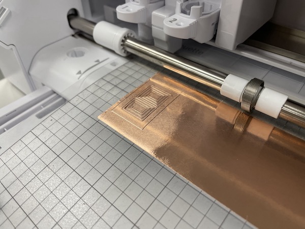
Figure 5: Cut!
I used a medium pressure setting for the cutting blade and only a single pass.
Since the copper tape has a sticky back, sometimes some glue can accumulate on the blade. This can result in the cutting tool dragging the copper foil all over the place (especially if you have small intricate features). In this case, clean the bottom of the cutting tool and the blade using some rubbing alcohol and start over again.
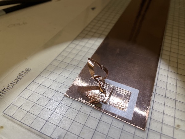
Figure 6: Remove excess material.
Once the cut is finished, the excess material needs to be removed. Use some pointy tweezers to lift off the unwanted parts of the coil. This is were the rectangular box comes in handy. It makes removing the excess material around the actual coil much easier. Be careful to not lift the coil off the backing paper. This is a tricky task, since the adhesive of the coil easily sticks to the tweezers. If that happens, gently push the coil back onto the backing paper and clean the tweezers with some rubbing alcohol in case some of the adhesive got stuck to them.
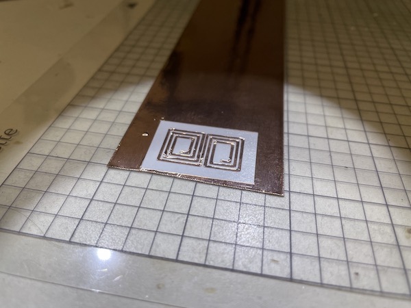
Figure 7: The finished NMR coil.
Once all excess material is removed to coil is ready to be lifted off the paper backing of the copper tape.
Lifting the Coil
Before the coil can be mounted on its support tube, it has to be lifted off the paper backing. For this I use a clear transfer tape. Cut a piece of transfer tape slightly larger than the out dimensions of the coil and place it on top of the coil. Press on it to make sure the transfer tape sticks to the coil and gently lift up the transfer tape. The coil should come off the backing paper and will stick to the transfer tape.
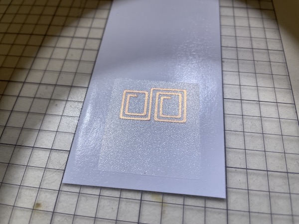
Figure 8: Lift coil using transfer tape.
Once you have figured out the optimum cutting parameters, it is easy to produce several copies of the desired coil in minutes. To store them for future use, use some of the backing paper to place the coil together with the transfer tape on it.
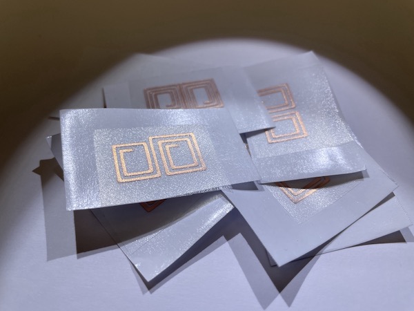
Figure 9: Plenty of NMR coils in minutes ...
Mounting the Coil
The coil produced by the vinyl cutter is not a free-standing coil and needs a support tube (for cylindrical coils). This can be a glass or plastic tube. Here, I’m using a sleeve made from Kel-F. Kel-F is a sturdy polymer, which does not contain any protons. It is commonly used in NMR probe heads when proton background signals have to be kept at a minimum. However, Kel-F is a fluorinated polymer, so not a great choice for fluorine NMR spectroscopy.
Before placing the coil onto the support tube clean the tube with some rubbing alcohol. Make sure the solvent is completely evaporated before placing the coil onto it.
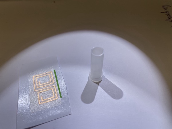
Figure 10: NMR coil and support tube.
Placing the coil on to the support tube needs some practice. The adhesive on the copper tape if very sticky. Once it touches the support material it will stick and you won’t get another shot to correct the position without either destroying the coil are causing wrinkles in the traces.
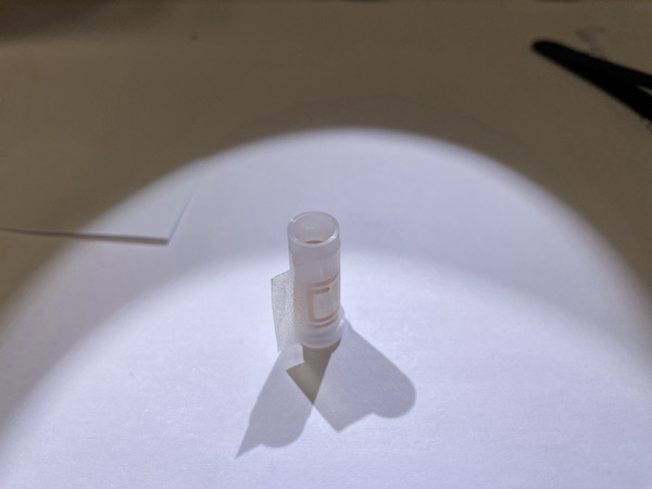
Figure 11: Place/transfer coil on to support tube.
To accurately position the coil on the support tube I first make sure that the bottom of the transfer tape has a clean, straight edge, parallel to the bottom trace of the coil (indicated by the green line in the figure above). I cut a straight edge with a scalpel through the transfer tape along the green line 1 mm away from the bottom trace of the coil. I use this straight edge to align the transfer tape with the bottom edge of the support tube.
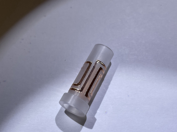
Figure 12: The finished coil
Once the coil is accurately aligned on the support tube, wrap the transfer tape with the coil around the support tube and Firmly press the coil onto the support tube. Gently lift off the transfer tape, the coil should stick to the support tube. Once the transfer tape is completely removed you can integrate the coil into the NMR probe.
Update, April 17th, 2022
CAD Model for Inventor
I had a few people inquire about the CAD model of the coil and I decided to put it on the website for download. Please keep in mind, this model comes as-is. It is by no means perfect and you may have to tweak it to use it for your individual project.
Three Turn Coil CAD Model: Download
The part is created in Autodesk Inventor. The last time I checked it I used Inventor 2021. For reference, the next figure shows a screenshot of the the three turn coil model.
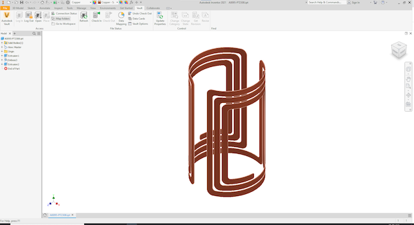
Figure 13: CAD Model of Three Turn Coil from Download
The complete model is parameterized so the coil diameter, length, trace width can be changed in one location and the model is automatically updated. This works to some extend pretty well, however, there is no error check. A model with a trace width of 0.5 mm and a fillet of 5 mm radius will not work and you will get an error. My apologies, some unites are in empirical units others are in metric units (the fun one has as a European scientist living/working in the US).
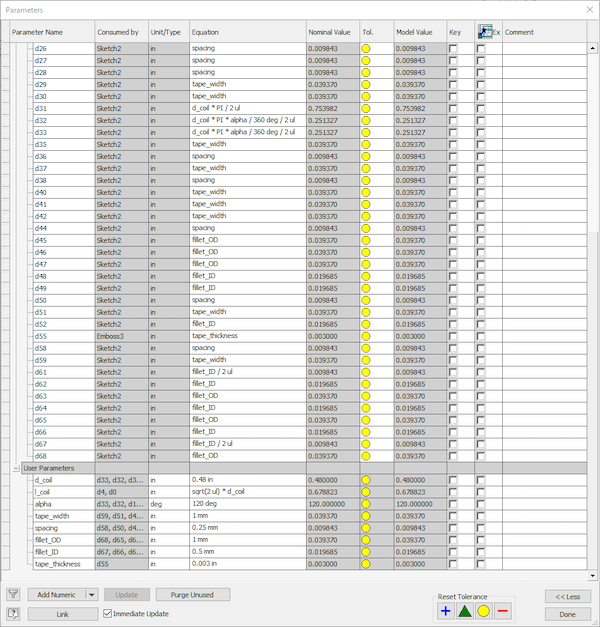
Figure 14: CAD Model Parameters
To access the parameters in Inventor to to Manage and the Parameters. This will open another window, as shown in the next figure. Most parameters are calculated from the User Parameters, which can be found all the way at the bottom of the list.
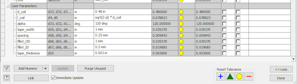
Figure 15: Coil Specific Parameters
Scroll down to User Parameters. There you will find the following parameters:
- d_coil: Coil diameter (in).
- l_coil: Coil length. The length is calculated from the diameter and is set to sqrt(2) * d_coil for optimum homogeneity. This can be changed if needed.
- alpha: Window opening angle. An opening angle of 120 deg. is optimum to achieve maximum B1 homogeneity. However, this sometimes needs to be adjusted. For this model of a three turn saddle coil, the angle is measured between the center vertical conductors of the coil.
- tape_width: Width of the individual traces.
- spacing: Spacing between traces.
The next two parameters are a bit “hacky”. Depending on your vinyl cutter the blade swivels and turns with the orientation of the cut. This seems to be the case for the Cameo 4. The blade gets dragged by the cutting head and this (and the age of the blade) determines the minimum cut radius.
This is different from other makes such as some of the Cricut models, which actively turn the blade using an additional stepper motor. I don’t have access to such a cutter, but I could imagine that having control over the blade orientation is a big advantage when cutting intricate features.
I’m using a Cameo 4 cutter and the fillet size is a bit arbitrary. You have to do a bit of trail and error to find the smallest radius your cutter can cut. Alternatively, you can change this to a chamfer which may be easier to cut.
- fillet_OD: Fillet radius of the outer corners.
- fillet_ID: Fillet radius of the inner corner.
- tape_thickness: This parameter is only used to extrude the copper tape. It is not used in any of the calculations. If you are using 3 mil copper tape (76.2 um) I assume that the thickness of the tape is negligible, compared to the coil size.
Once you adjusted all parameters it is good probably a good idea to just print the dxf file at a 1:1 scale on a regular printer to confirm all dimensions are correct before attempting to cut it.